


厂商 :深圳恒通未来科技有公司
广东 深圳市- 主营产品:
- CWDM波分复用器
- DWDM密集波分复用
- OEO光纤放大中继器
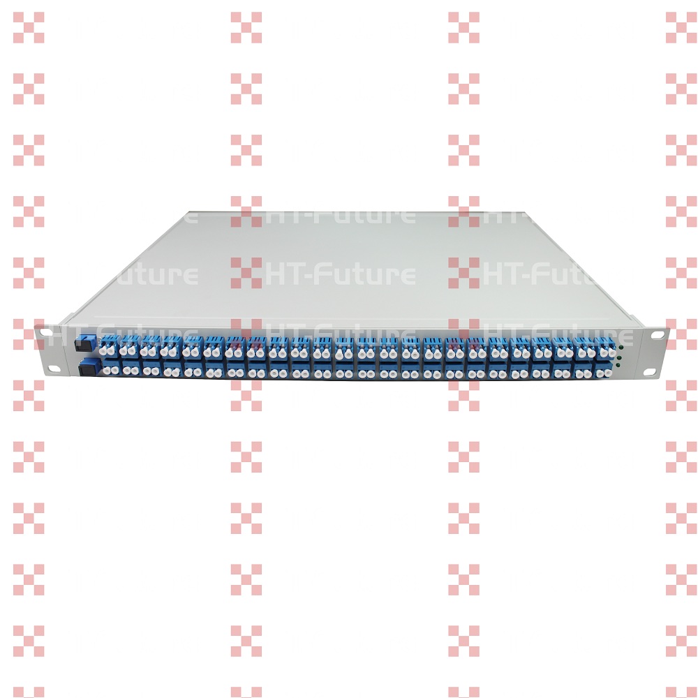
HTFuture 80 CH 50G DWDM AWG
This document presents the generic specification for the 80-channel 50GHz Athermal AWG MUX/DEMUX Rackmount supplied for use in DWDM system.
Athermal AWG(AAWG) have equivalent performance to standard Thermal AWG(TAWG) but require no electrical power for stabilization. They can be used as direct replacements for Thin Film Filters(Filter type DWDM module) for cases where no power is available, also suitable for outdoor applications over -30 to +70 degree in access networks. HTFuture’s Athermal AWG(AAWG) provide excellent optical performance, high reliability, ease of fiber handling and power saving solution in a compact package. Different input and output fibers, such as SM fibers, MM fibers and PM fiber can be selected to meet different applications. We can just offer 19” 1U rackmount package for 50G AWG products.
The planar DWDM components(Thermal/Athermal AWG) from HTFuture are fully qualified according to Telcordia reliability assurance requirements for fiber optic and opto-electronic components (GR-1221-CORE/UNC, Generic Reliability Assurance Requirements for Fiber Optic Branching Components, and Telcordia TR-NWT-000468, Reliability Assurance Practices for Opto-electronic Devices).
Features
l Low Insertion Loss
l Established silica-on-silicon
l Low PDL
l Low chromatic dispersion
l Telcordia GR-1221-CORE qualified
Applications
l DWDM transmission
l Wavelength Routing
l Optical add/drop multiplexing
Optical Specification (Flat Top Athermal AWG)
|
Parameters |
Specs |
Units |
||
|
Min |
Typ |
Max |
||
|
Number of Channels |
80 |
|
||
|
Number Channel Spacing |
50 |
GHz |
||
|
Cha. Center Wavelength |
C -band |
nm |
||
|
Clear Channel Passband |
±6.5 |
nm |
||
|
Wavelength Stability |
±0.05 |
nm |
||
|
-1 dB Channel Bandwidth |
0.2 |
|
|
nm |
|
-3 dB Channel Bandwidth |
0.3 |
|
|
nm |
|
Optical Insertion Loss at ITU grid |
|
6.0 |
7.0 |
dB |
|
Adjacent Channel Isolation |
25 |
|
|
dB |
|
Non-Adjacent, Channel Isolation |
30 |
|
|
dB |
|
Total Channel Isolation |
20 |
|
|
dB |
|
Insertion Loss Uniformity |
|
|
2.0 |
dB |
|
Directivity(Mux Only) |
40 |
|
|
dB |
|
Insertion Loss Ripple |
|
|
1.5 |
dB |
|
Optical Return loss |
40 |
|
|
dB |
|
PDL/Polarization Dependent Loss in Clear Channel Band |
|
0.3 |
0.5 |
dB |
|
Polarization Mode Dispersion |
|
|
0.5 |
ps |
|
Maximum Optical Power |
|
|
23 |
dBm |
|
MUX/DEMUX input/ output Monitoring range |
-35 |
|
+23 |
dBm |
|
Operating Temperature |
-5 |
+25 |
+65 |
℃ |
|
Operating Humidity |
5 |
|
95 |
%RH |
|
Storage Temperature |
-40 |
|
+85 |
|
|
Storage Humidity |
5 |
|
95 |
|
|
Package Size |
L150×W65×H16 |
mm |
||
IL Represents the worst case over a +/-0.01nm window around the ITU wavelength;
PDL was measured on average polarization over a +/- 0.01nm window around the ITU wavelength.
Ordering Information
|
AWG |
X |
XX |
X |
XXX |
X |
X |
X |
XX |
|
|
Band |
Number of Channels |
Spacing |
1st Channel |
Filter Shape |
Package |
Fiber Length |
In/Out Connector |
|
C=C-Band L=L-Band D=C+L-Band X=Special |
16=16CH 32=32CH 40=40CH
48=48CH
XX=Special |
1=100G 2=200G 5=50G X=Special |
C60=C60 H59=H59 C59=C59 H58=H58 XXX=special |
G=Gaussian B=Broad Gaussiar F=Flat Top |
M=Module R=Rack X=Special |
1=0.5m 2=1m 3=1.5m 4=2m 5=2.5m 6=3m S=Specify |
0=None 1=FC/APC 2=FC/PC 3=SC/APC 4=SC/PC 5=LC/APC 6=LC/PC 7=ST/UPC S=Specify |


